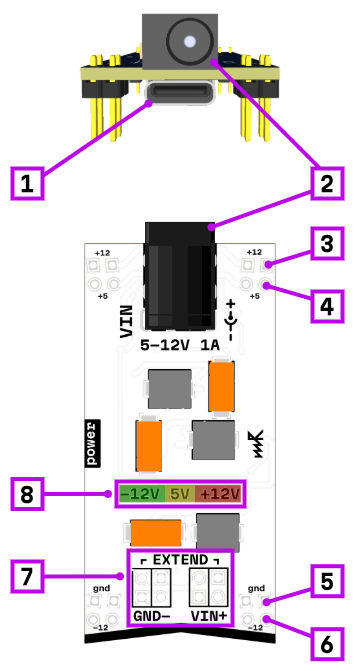
Provides +12, -12 and +5V power via USB-C or DC jack input. Has chaining capabilities.
 Documentation: modules — power
 Product page: microrack — power
Provides +12, -12 and +5V power via USB-C or DC jack input. Has chaining capabilities.
Documentation: modules — power Product page: microrack — power
Is there a recommended list of types of power supplies to use with the power module and ones that aren’t suitable? I’m thinking about optimal voltage, current capability and voltage drop but perhaps noise is relevant too? I’ve been using a USB type A connector (blue USB3) on a desktop computer, one built-into a power strip and a power bank and while everything worked I was surprised by how much voltage drop there can be with eight modules.
On the design front, I see the v1.3 module is using a TPS62933DRLR to generate the +5V rail from whatever voltage comes in. Given the input voltage will have dropped across the schottky diode and there will be some degree of drop at the power supply and across the lead from 5.0V it looks like the choice of a buck converter prevents generation/restoration of 5.0V will impact to the +5V rail? I see quite a few schematics showing use of linear regulators on the modules to make a clean local 5V supply so perhaps this has less impact than one might think?
I just measured a few power sources at the GND- VIN+ pins and at +5V rail with a multimeter and aforementioned 8 module load, here are the numbers in descending order:
Was a buck/boost converter considered for making the +5V to deal with, say, 3V-13V input?
For the power rail indicators (LEDs for +12V, +5V, -12V) I think it would be nice if they could indicate approaching overload. Something like green for good, amber if there’s some level of voltage drop and red for overload/overtemp/short-circuit protection. Amber would mean you have too many modules plugged in. All LEDs off would then mean unpowered. For that scheme the three LEDs with the current single contiguous PCB window would benefit from two separators to make the three sections more obvious.
I prefer to use any usb-c power adapter or powerbank which has at least 9 V PD or any usb-a with quick charge. It provides you 9 or 12 V so you can get more power.
Powering from laptop or old 5V-only adapter is possible but as you already noticed 5V rail drops, overall power capacity allows you to powered up no more than 5-6 modules, also power module starts to heat more so I don’t recommend to use this way.
you’re right, in some cases like bad usb cable + 5V source it can drops down to even 4 volts.
I don’t recommend to put any sensitive load to +5V. It is useful for LEDs, for digital circuitry (except you get some CV/gate signals directly from digital ICs), also to powering some 3.3 V loads through LDO (like ESP32 or another MCUs).
If you need to get reference 5V on the module, I recommend to use local LDO on the module itself.
So I’m not sure we need to put buck/boost converter, just keep in mind +5V rail is unstable, noisy and voltage can drops.
That’s a good idea!
After having a lot of experience working with power module I also think it will be good to put green LED on every rail but change color to yellow in case of approaching overload and red in case of short circuit. But for now I don’t know how to make good but cheap schematic that controls the current consumption.
I’ve seen the (voltage) advantages of the buck/boost with the Pi Pico. The input voltage is so flexible and can be lower than the microcontroller’s 3.3V and it all still works well. I think the chip they use is lower current than the buck one on the Microrack power module at the moment.
The electrical specification also has
Voltage tolerance: ±10% on all power rails
For the +5V rail that’s 4.5V to 5.5V. For my measured examples even a good quality PSU like the 15W Raspberry Pi one (5.1V, 3A) can’t conform to that specification with an 8 module load - I measured 4.46V on the +5V rail.
When I first started using Microrack I was using my desktop’s type A USB (blue USB3) which can provide about 1.5A. That measures just 3.67V (I have a few more measurements in step 3) which I was blissfully unaware of. Everything seemed to work okay but it’s way out of spec, there’s likely to be further drop from schottky protection diode, any 3.3V regulators might have too much drop, perhaps some ICs won’t like it and it’s starting to get close to Vf for any white/blue LEDs. If people design their own modules to the Electrical Specification then these may not work okay.
I just took a look the midi→cv schematic and it looks like +5V goes into schottky diode then AMS1117-3.3 for the module’s 3.3V when the local USB isn’t powered. With 3.67V that’s perhaps -0.25V and then -1.1V (typ.) = 2.32V.
Issues could be invisible for anyone developing modules and testing them only using 12V via USB-C (or power jack).
I think it’s worth soliciting more views on this and in the meantime adding some recommendations for good PSUs and ones to avoid in the documentation.
BTW, for going from +5V to 3.3V (ex-TI) John Teel has a few issues with the AMS1117 including not putting the L in LDO and transient response being poor and cites WiFi transmissions having potential to cause problems due to that.