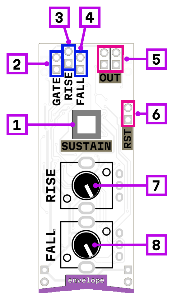
Envelope generator with rise and fall control, sustain AR and no-sustain AD modes, rise and fall modulation.
![]() Documentation: modules — Envelope
Documentation: modules — Envelope
![]() Product page: microrack — Envelope
Product page: microrack — Envelope
Envelope generator with rise and fall control, sustain AR and no-sustain AD modes, rise and fall modulation.
![]() Documentation: modules — Envelope
Documentation: modules — Envelope
![]() Product page: microrack — Envelope
Product page: microrack — Envelope
Cv inputs for rise and fall with the ability to to loop the evolope ![]() question is how fast can this thing go?!
question is how fast can this thing go?! ![]()
Also something like this would be a great teaching point. I remember the first time i came across “end of cycle trigger” didn’t have a clue for months what that was typically used for as id been accustomed to having a switch or button simply labelled “loop”. Then i quickly realised damn this isn’t just a fun new flexible modulation sorce but its also a whole new sound source as well! I think its things like this people miss out on
We have issue with time range right now, but the range can be fixed by tuning of the resistor values. I plan to implement rise/fall time from about 30 second up to 0.005 second (200 Hz), so you can use this module as LFO and even as signal oscillator
Hooray, big description update!
Wow, this is a flexible module!
At first I didn’t think much of it: one of those simplified envelopes, where you need two of them to build an ADSR. But often a two-stage envelope ist sufficient, and this analog gate input opens up so many more uses!
Versatility of the modules is what distinguishes a modular system from a sawed-apart monosynth. ![]()
I was inspired by Buchla envelope, Makenoise Function and another same ad/ar envelopes
Good news: envelope generator is ready!
Rise and fall time changes from 40 s to 10 ms, so you can use this module as envelope, as LFO, as slew limiter and as envelope follower.
I really like the result and I can’t wait for you to appreciate it too.
The output does a small “jump” at the start of each flank, which goes unnoticed in most applications, but is very obvious when used to modulate delay time (trying to build a flanger). It does not do that in sustain mode (but then it will not work as an LFO of course).
I have no idea what causes this effect, but then the envelope is one of the more complex circuits.
I will investigate source of this jump. Maybe this is because of not perfect match between charge and discharge transistor circuits
I have talked to a real electrical engineer (instead of just a hobbyist like me) about the circuit and we’ve come to several conclusions:
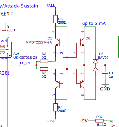
Of course this is all just theory and needs to be checked with the datasheets and, ultimately, with an oscilloscope. But maybe a capacitor from pin 1 of SW1 to ground (forming a lowpass together with R32) would mitigate the problem already.
Edit: I did some homework: the LM358-datasheet gives a maximum slew rate of 0.5V/µs, so a 12V jump would take 24µs. The NE555-datasheet says: rise time is 300ns, but that is a digital signal, so 300ns is the time between 10% and 90% of the new output level; no word about the remaining 20%. But it should be done in unter 2µs, which means that it takes U3.2 about 22µs to catch up, and during this time an uncontrolled current is injected into C1, making the voltage jump.
Moving SW1 to the input of U1.2 instead of the output would solve the problem, but I’ll still try the capacitor as a feasible fix for the already existing modules.
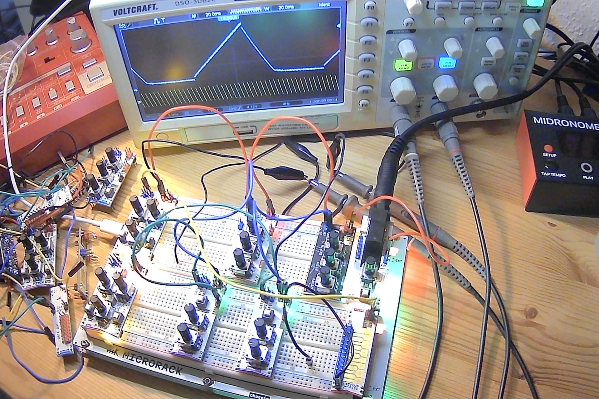
Edit again: here is the 'scope screenshot I should have provided at the beginning. Output of the envelope module in A/D mode at the top of the curve. The jump (ca. 0.4V) happens wthin 25µs, as expected more or less.
The first part of the jump looks almost linear, ca. 300mV in 12µs, which amounts to 25mA at C1, five times more than expected for normal operation.
Yet another edit: The env could also use one of those universal gates (or anything with a schmitt-trigger input) in the trigger path for the A/D mode (before C2/C3). That would guarantee a steep enough flank to trigger C2/C3 - R49 - U7 , even for very slow input signals. Probably C2 and C3 could then be smaller.
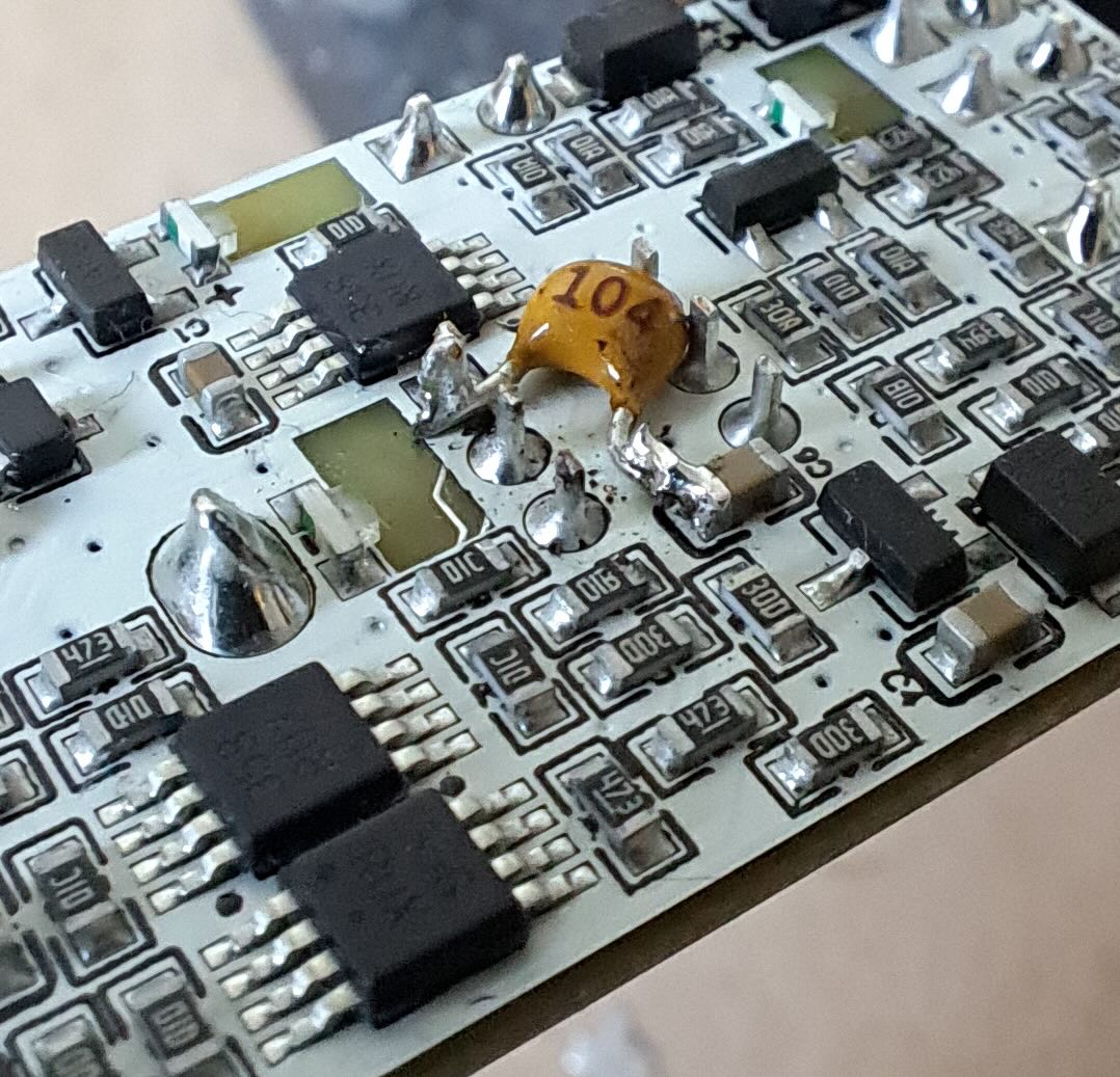
Update on the “jump” at the start of each flank: I soldered a capacitor (100nF) from SW1, pin 1 to GND, which seems to help a lot.

oh wow!
I want to make the same fix, will come back to you with the results.