This is a weird question more about the MicroRack standard than about the modules themselves. If it was answered somewhere else, I’m sorry; I couldn’t find it.
The measurements for the modules are measured in pins; I dig this. HOWEVER, are we referring to the horizontal rows or the vertical power bus rows?
I am not totaly sure what exactly you are asking here, to be honest
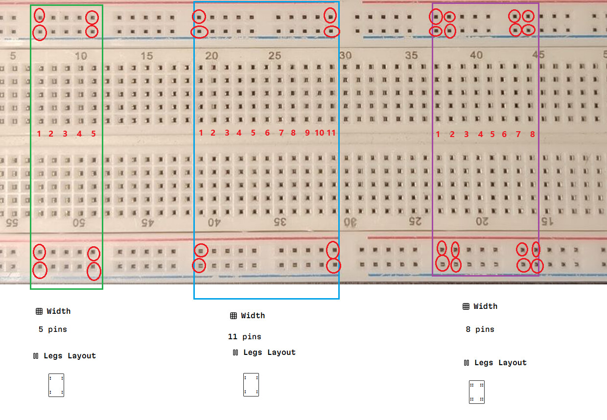
But that’s how I understand different widths would look like on the breadboard:
(I’d seen prototypes of the microrack modules in person at their presentation and even played some sound with it, so I believe I remember that good enough to draw the correct picture)
Microrack modules are using only pin holes on the power lines. top and bottom, all other pins are never connected to modules.
Power bus has gaps betwen pin blocks, but each gap is the same size as one pin, and still counts as part of the width for the module installed.
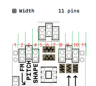
Here is the 11 pin VCO module which is indeed fitting 11 standard pins, which would take two 5-pin sized power blocks + 1 pin sized gap between them:
Hope it answers your question somehow.
1 Like
That’s what I was thinking, but I wasn’t 100% certain. I’ll admit, I looked at a cheap breadboard in comparison to a nice one and my cheap one was inconsistent on the spacing when compared to that nice one.
Just compared the boards to my other ones. Makes more sense now. That one board I have is just out-of-spec.
1 Like
At some boards I see power pins to have offset relative to the regular pins. (usually half of a pin offset, so power pins are just in the middle between regular pins on horizontal coordinates)
But this offset should be constant and spacing should be the same. At least for what I’ve seen so far.
Considering that we are using only power pins anyway, it does not matter if the rest of the board is shifted or not, if power bus is consistent to itself and it’s twin brother power bus.
For sure I would not bet a lot of money that there are no exotic breadboards in existence with no consistency at all, but to my guess it should be really unlucky to get one.
UPDATE:
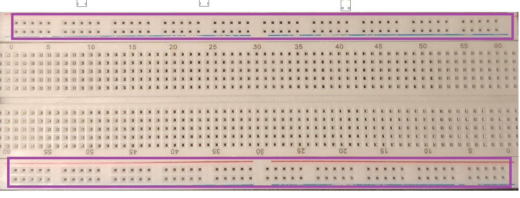
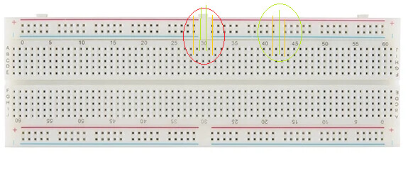
I’ve found image of a breadboard with 2 pin gap in the middle, while rest of the power bus has 1 pin gaps between blocks. (generic pin spacing is the same though) Surprise.
Be careful guys and look into your breadboard before forcing modules into breadboard, heh.
1 Like
Check if the power bus actually runs the full length. I’ve seen breadboards with the power lines split in two halves. That can be a nasty surprise.
2 Likes
World is a scary place to live in. I’ve also seen breadboard with misplaced metal inserts, so that you can break your device pins when trying to use it.
Before using actual modules with a new breadboard, I would try using something like this first
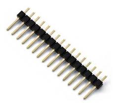
Just to be sure that breadboard is okay, and to align metal inserts if they are off-center a bit.