Voltage controlled oscillator with three waveforms, modulations and low frequency mode.
 Documentation: modules — oscillator
 Product page: microrack — oscillator
Voltage controlled oscillator with three waveforms, modulations and low frequency mode.
Documentation: modules — oscillator
Product page: microrack — oscillator
Hi. I would like to ask what is voltage range for the Pitch input? Is it bipolar or unipolar?
And what voltage corresponds to A4 440hz wave?
All CV voltage is in range from -5 to +5 volts, 1 V/oct.
Base oscillator frequency is tuned by pitch knob.
Any chance we might be able to get a sync/reset input? Would come in handy in lfo mode and who doesn’t love some hardsync.
Yes, we plan to add sync input in release version. Adding the hardsync will be simple, but I will think about softsync input also.
Would be there anything for a sine wave, btw?
Maybe we should have made a stretch goal out of it 
Hello!
We have a great update on the VCO schematic. I found a current leakage of about 20 µA through the Schottky diode, which caused the 1V/oct law to go out of tune, even at the second octave. After changing the diode to a BAV99, we now have 6-7 octaves perfectly tuned!
Also, the LFO range has become wider, and the oscillator can produce an ultra-long period of up to 1 minute!
Now I’m working on the triangle converter, hard sync input, and output levels.
After a lot of work, we’ve finished debugging the VCO module!
So, triangle output is implemented, hardsync works, output levels is 0…5 or -5…+5 with 5% accuracy!
I don’t want to spam the jams thread with technical tests, so I’ll post this here, as it is about the oscillator: a playful way of testing the limits of oscillator stability, and… yup, there they are! 
Two oscillators, very slightly detuned (by a fraction of a Hertz), to get this flanger-like comb filter effect.
The oscilloscope shows one oscillator at the bottom (yellow) and the mix of the two at the top (blue).
The LFO (bottom right) triggers the envelope (bottom left) which controls filter cutoff. No VCA, as I didn’t want confusion on the scope screen.
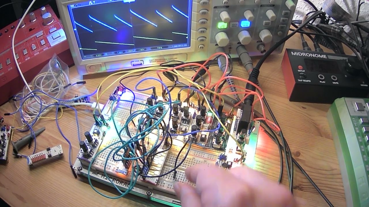
The oscillators are obviously pretty stable, but they seem to have slightly different ideas about intervals (the phase difference changes much faster at higher pitch).
At the end of the video I blew it I blew on it a few times (you can see the wires shiver) to change the temperature, and the beat frequency immediately changed. This is one setup where a good sneeze could destroy everything! (well, at least it would require ten minutes for temperature stabilisation and half a minute or so of tuning)
Edit: I made another video at a higher pitch, where the beat frequency drifts off rather faster.
I watched both videos and everything seems normal behavior for voltage-controlled oscs. You could try syncing them but then you would probably lose the detune, but worth trying either way
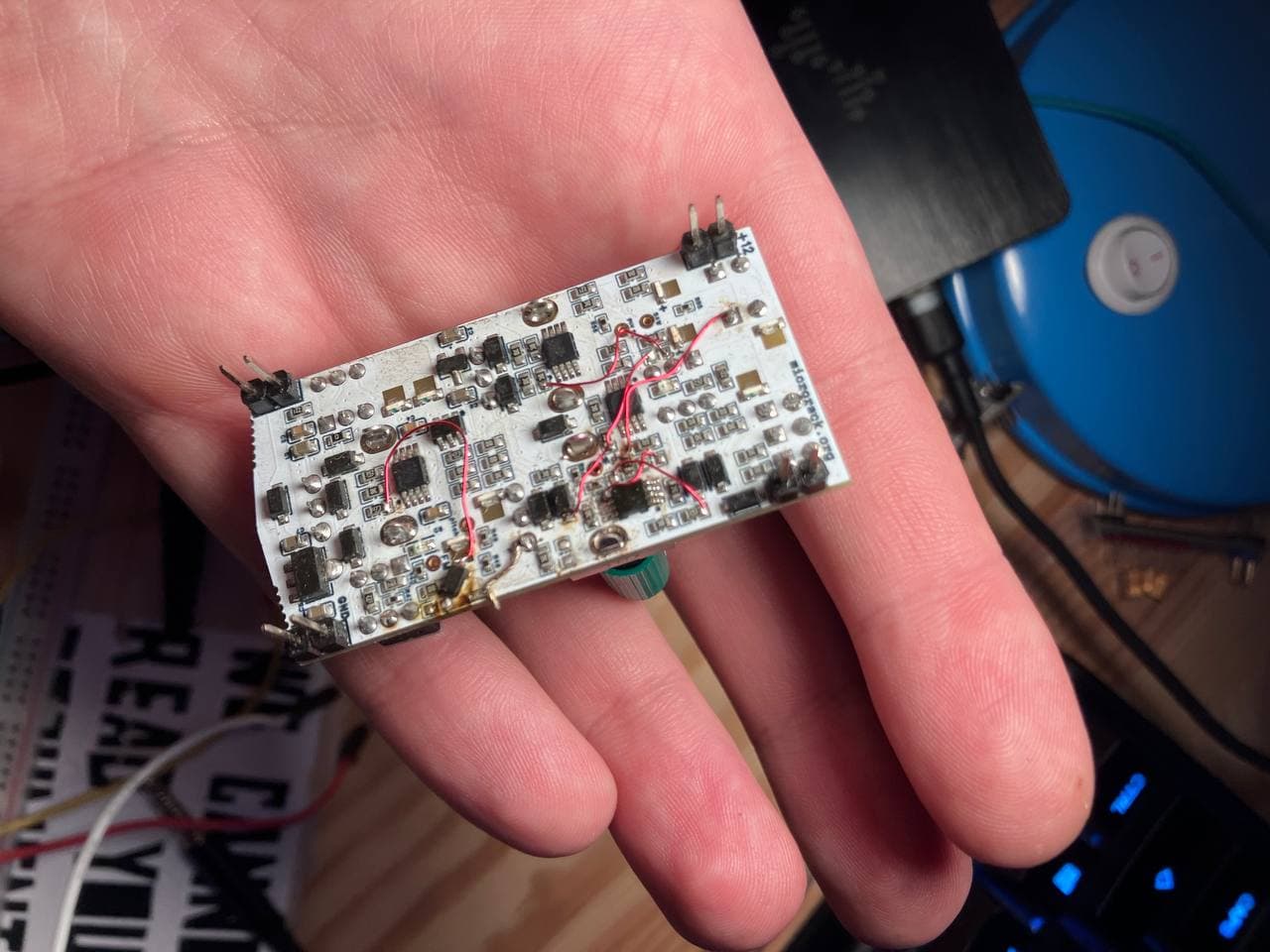
You’re right, oscillator is not perfectly stable: at first, you need to wait about ~2 min after power up before frequency become stable
and also it changes with temperature.
In next version I prefer to add thermistor to compensate temperature drift, we already received a prototype and I’ll check new version soon
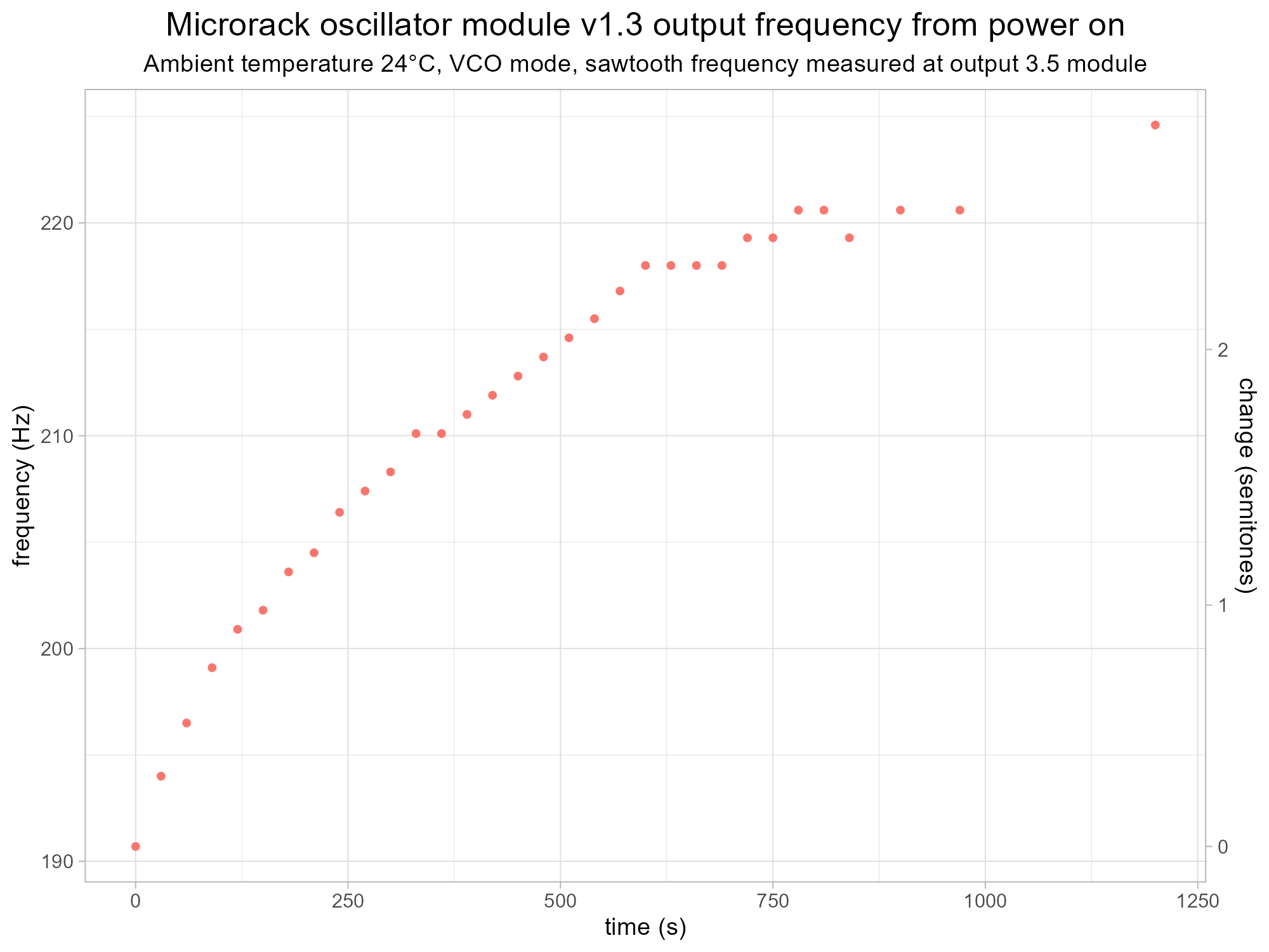
I did a quick check at my desk from power on of something I had previously tuned to about 220Hz. This is what it looks like. I thought it was done then it went up a bit more hence the gap in points.
I don’t know much about RC based relaxation oscillator stability so I threw the question at a popular LLM and it thinks “C0G/NP0 ceramic capacitors” are important. Are there other temperature effects in the semiconductors?
BTW, the schematic shows a SN74LVC2G17DBVR1 with an input for an unused logic gate not connected. Is that best practise? I had an interesting discussion a while back with someone whose product initially failed an EMC test due to oscillations from gates left with floating inputs.
It is a schmitt-trigger input, so that’s OK (a schmitt-trigger is made to accept analog voltages and snap to the appropriate digital level, with hysteresis for stability: it will take e.g. > 3V to switch to H and then <2V to go L again).
Apart from that last dot, your curve looks like a classic exponential decay, and it shows that 20 minutes of warm-up time (as recommended in many synthesiser manuals) are about the right time.
The most important temperature effect for a VCO is the base-emitter voltage drift in the exponential converter. That is ca. 2mV/°C, at a point where we have something like 30mV/octave, so it would be huge. In our VCO that is compensated by the double transistor (PNP as a voltage-follower, then the NPN as the actual converter).
The next effect changes the V/oct factor in the exponential converter; that is not compensated in the Microrack circuit, AFAIK.
Then there is the base-emitter voltage of Q3, influencing how far C1/C2 gets charged at each reset (the steep flank of the sawtooth).
And then there are all the other components; the capacitors (C1, C2), the resistors determining the comparator threshold (R22, R23, R24, R16, but they will compensate each other, if made in the same technology (carbon vs. metal)), and the comparator (U8.1): bias and output voltage swing.
Historically, analog synths often used heated transistors (constant temperature) for their exponential converters. There was a chip made for that purpose: µA726, temperature-regulated transistor pair, used e.g. in the Elektor Formant. That chip is not being made any more, so people built replacements with the CA3046 transistor array, which is also out of production by now, but there is a modern replica: AS3046, used e.g. in the modern replica of the Elektor Formant by Erica Synths. There are also transistor arrays by THAT company (e.g. THAT300) specifically made for audio circuits, but all those chips have one thing in common: they are too expensive for Microrack.
OTOH it is an interesting challenge to use only standard components and see how far one gets that way.
The documentation for the module suggests the output covers the range
bipolar (-5 to +5 V), unipolar (0 to +5 V)
From an (unloaded) output I see about 7.6V peak to peak on sawtooth and square waves for bipolar at SHAPE mid position. For triangle the story is a bit different with it shrinking as frequency increases.
That’s right, actual implementation not cover the ±5V range and we have to notice it in documentation and fix it in the next revision.
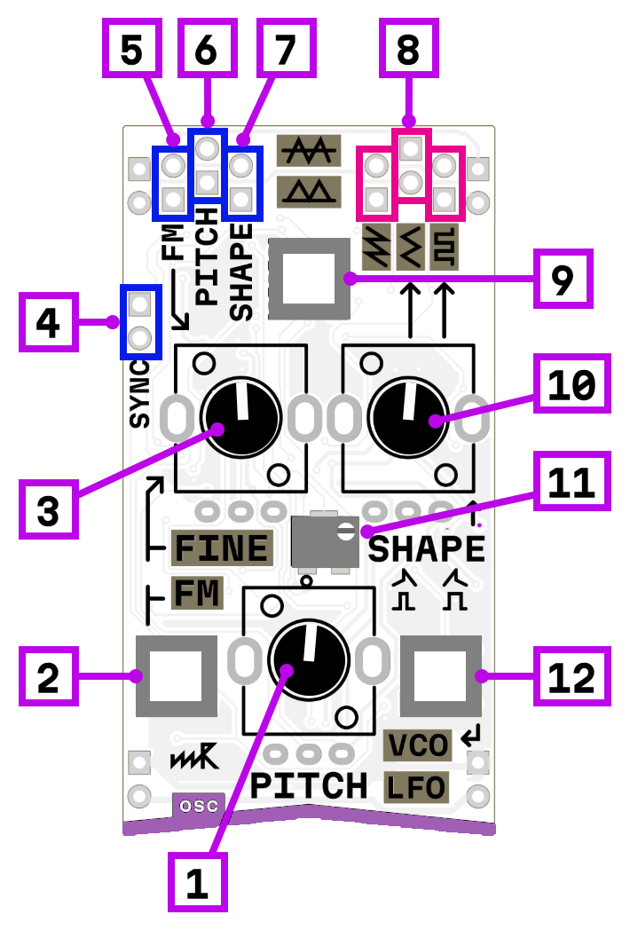
For the triangle: I put passive low-pass gate on triangle on purpose to make triangle output more soft and sine-ish. You can remove C12 to get raw triangle output or replace it into smaller one.