Hey guys. Microrack has huge DIY vibes, and adding some 3d printed parts and designs to the ecosystem feels natural. So let’s have dedicated topic for that.
2 Likes
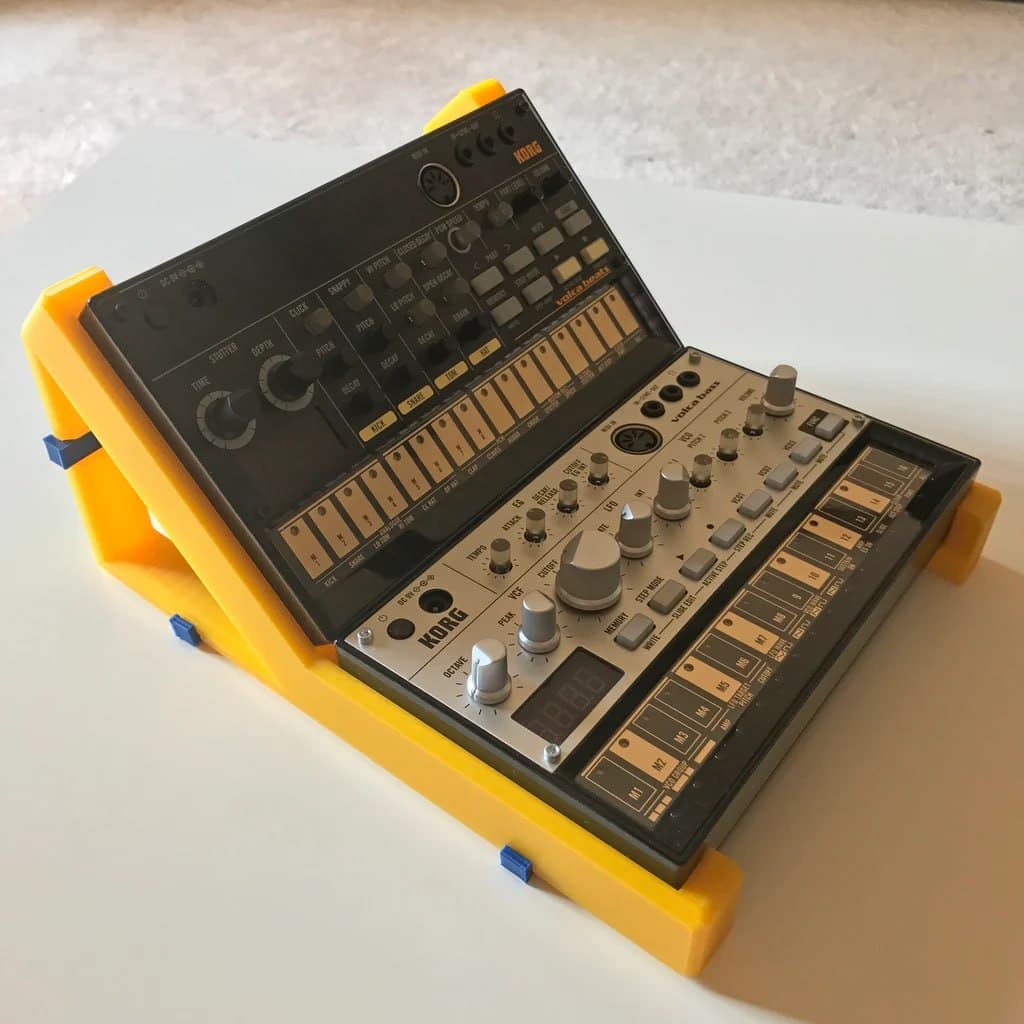
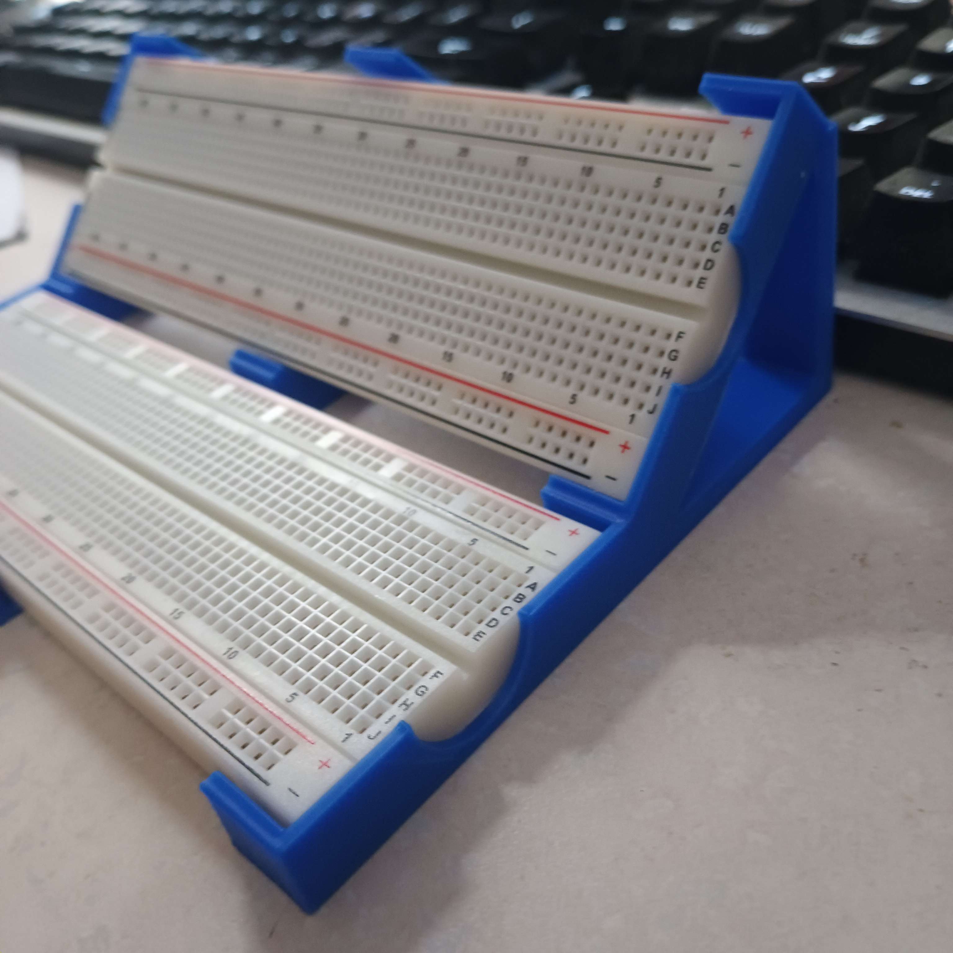
For now, I am thinking about breadboard rack similar to the ones that people already do for volca - like this one:
4 Likes
I might remix a thing or two.
Would be great if the 3d case would accommodate those of us who did not splurge for the Eurorack compatible rack ![]()
I’ve seen this panel Parametric Eurorack Panel by JonathanBedrava - Thingiverse in parametrical Openscad format (suitable for editing if you know Openscad’s source code language) . Might be used as a starting point, to slap some breadboard mount on top of it.
However it does not solve powering breadboard properly, which is I guess main point of having real custom chassis.
Either tonight or tomorrow, I’m going to see how a remix of this case works
Barring that, there are these DIN rail mounts I could make a frame around.
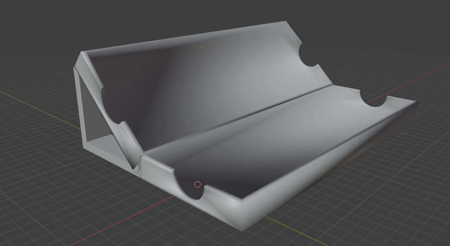
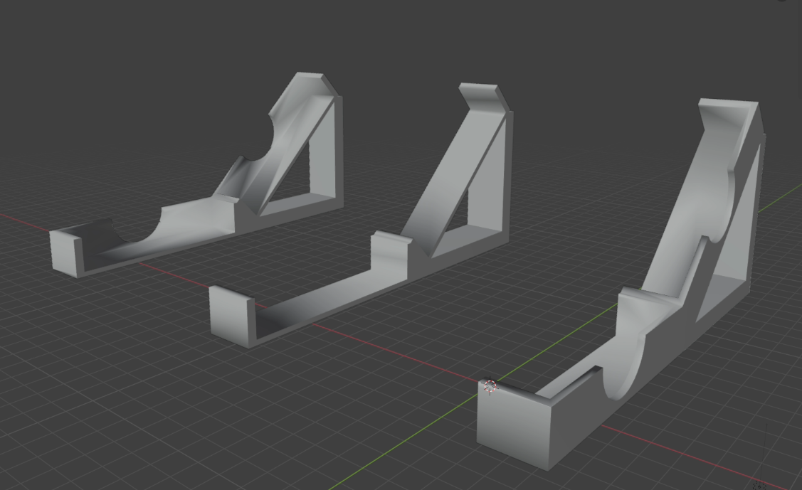
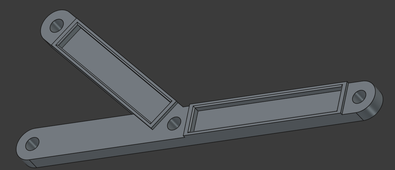
This is my first iteration in about 15 minutes of Blender. It’s something of a remix from someone’s tray (I had to cut so much away from the original and add so much, it’s barely anything other than stealing measurements – I’ll still credit anyone involved in the end). I’m thinking of making a little folding case, but my modeling skills are garbage, so it’ll take a while.
Any feedback is welcome.
1 Like
-
Looks like there is a gap between supporting column and upper box, at least on the screenshot.
-
And how about using space below the upper box for spare wires?
-
I am a bit worried about how this gonna be printed - upper box quite a steep unsupported. Maybe split to parts so flat bottom of the upper box could be printed flat on the printer table?
For the folding box we need to know how much space above the breadboard is requried to keep knobs and wire pins safe from bending too much and damaging.
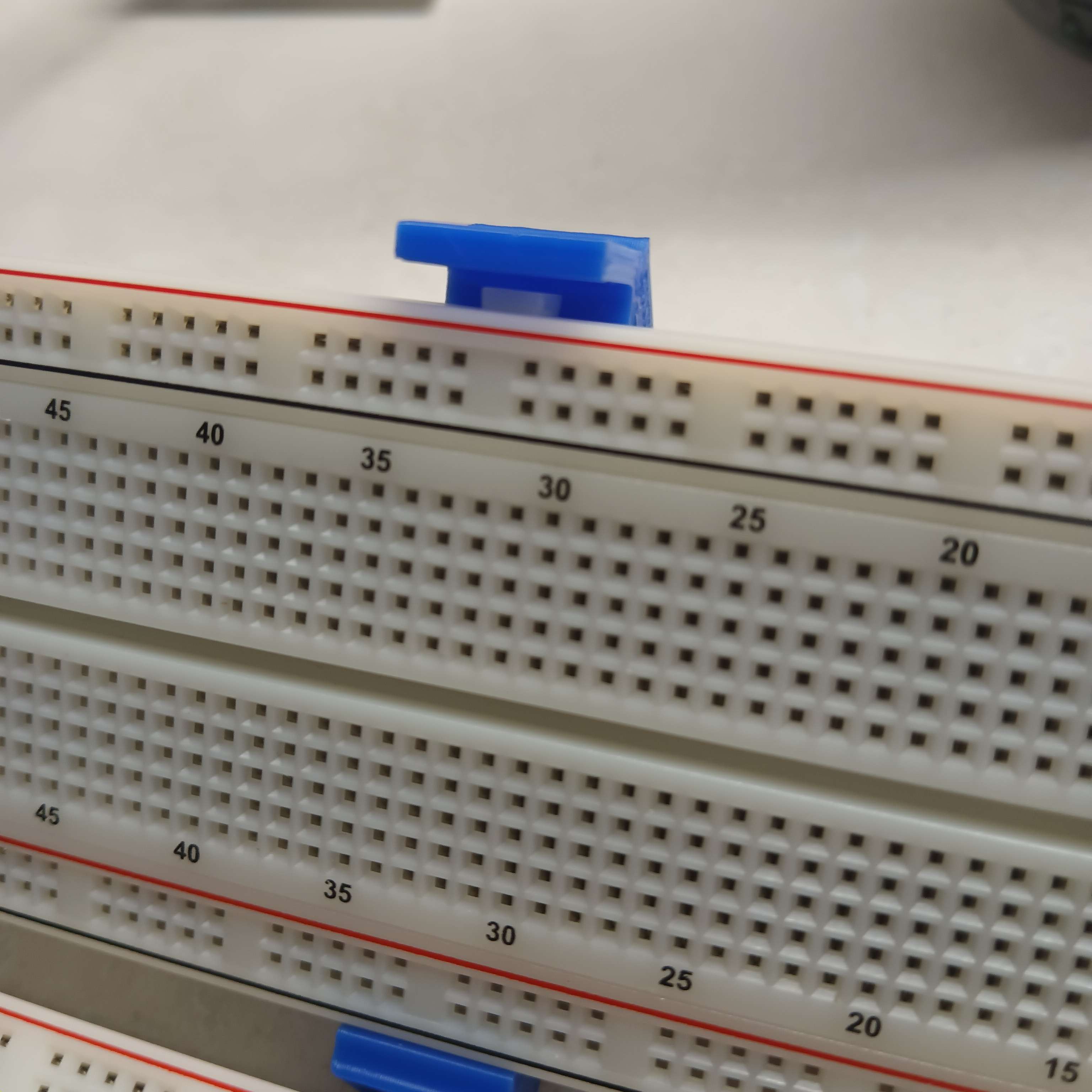
From my side I am trying to explore minimalistic design with metal rods like this ( I know it is a smaller breadboard, but do not have 830 breadboard right now and ends still should have the same sizes)
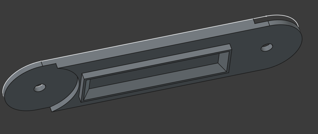
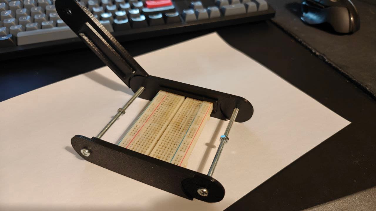
What is not really helping - these interlocking tabs are kind of ruining the clean rectangular shape of the breadboard.
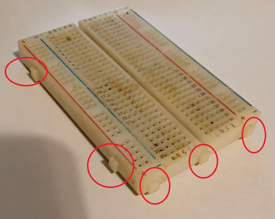
I have a huge suspicion that these connector tabs are even not fully standartized - I thinkig I’d owned incompatible breadboards from different venods that cannot be joined because of the different tabs, but I do not remember HOW different they were. Was it just a small difference in shape, or are they in completely different places.
It makes one-for-all case development more complicated. Maybe I would end up just cutting off these parts from the breadboard, but it feels like vandalism.
I mean for one we can assume that everyone will at least have one from Microrack, but other than that, I would imagine that one will be willing to lose some horizontal space to fir the breadboard in that design.
The main gripe I would imagine with a “sit in” design is that it’s difficult to design something that will amke sure the breadboard sits tight, but at the same time allow easy non-destructive removal
Long post- TL;DR: I’m making 3 designs that should all accommodate 830 boards.
I’m really liking the feedback and definitely will take it into consideration.Admittedly, I did slice it with some support; I plan on only using 3d printed parts. There’s no gap there; I just didn’t finalize that area because of potential feedback on the angle of the top section. With tree supports, it’s 94g (35.45m) and just over 11 hours on my Ender5S1 on standard quality using ABS.
I was kinda intending on the back side being somewhere you could just lay some cables flat; I can definitely make a sort of tray to fit under there.
The tabs for breadboards aren’t standardized insofar as I can tell, but they’re typically of the same length and height; it’s the width and contour that make it not universal. I have three different variants on the desk in front of me: lets call them wide rectangular, narrow rectangular, and narrow rounded. Of course, it’s something of a crapshoot to see if they actually interconnect. That’s entirely on the long edge; 830 boards don’t have short-side connectors; only the 400 breadboards seem to have those. Admittedly, there are a LOT of breadboard station designs and a LOT of them have instructions to cut the tabs. I’m not going to be asking people to grab a Dremel. Because tab spacing is uniform, I only have to accommodate the geometry of the largest tabs for the slots.
I’m working on a version more akin to the one in the OP as well as a folding variant with some clips that function more like a travel case.
LUCKILY the distance between the edge of the board and the tab seems to be somewhat standardized, so I do have some wiggle room to design a tab that fits over the +/- labels. This means that I can cut into the joint at the middle of the two cases to include a singular slot for both breadboards’ tabs (so bottom board would be tabs up, top board would be tabs down).
The travel case will be my third design because, as mentioned, I need to figure out all of the heights. I’m not planning on having it transport with jumpers still in, but module height will absolutely make all of the difference.
The minimalist design will require a little cutting and design, but is pretty straight forward. It’ll print flatter and faster.
I’ve got to recalibrate my printer and try to get this ABS to work. It may just be slagged from the humidity; I’ll be ordering some PLA+ tonight so I can print a bit faster.
2 Likes
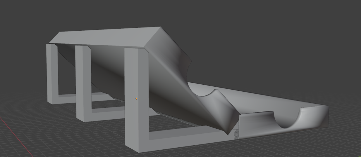
The minimalist is going to be largely based on the one I shared, but will have much less material and printed.
I don’t have the crossbars designed yet, BUT…
1 Like
That’s a noble approach, I totally agree that there should be at least one completely 3d printable design choice, not relying on hardware or additional components.
Great news for me. I’d missed that one , and looks like it is hard to find even one 830 board photo with tabs on the short side. This makes my design more viable, so I would try to grab couple of 830 breadboards at Saturday to try it in practice.
Hmm. This one looks printer friendly so far, with completely zero overhangs. Cool. Interesting what are you going to do with the these crossbars.
Btw I forgot to mention that I like these round cutouts. I suppose it is intended to ease inserting or removing the breadboard?
The cutouts were part of the original model I started from. Legitimately, it was just a tray for breadboards and a Raspberry Pi. Yeah, it’s to lift them out. Less critical on this minimal design, but it also acts as a bit of weight relief and ease of access if you don’t want to disassemble or flip the rack. It also just keeps it consistent.
The idea is that the end pieces will be printed with the cut-out side on the bed with the middle being both optional and able to be printed on either flat size. The crossbar supports will be integrated into reinforced areas I’m going to put in.
Okay.
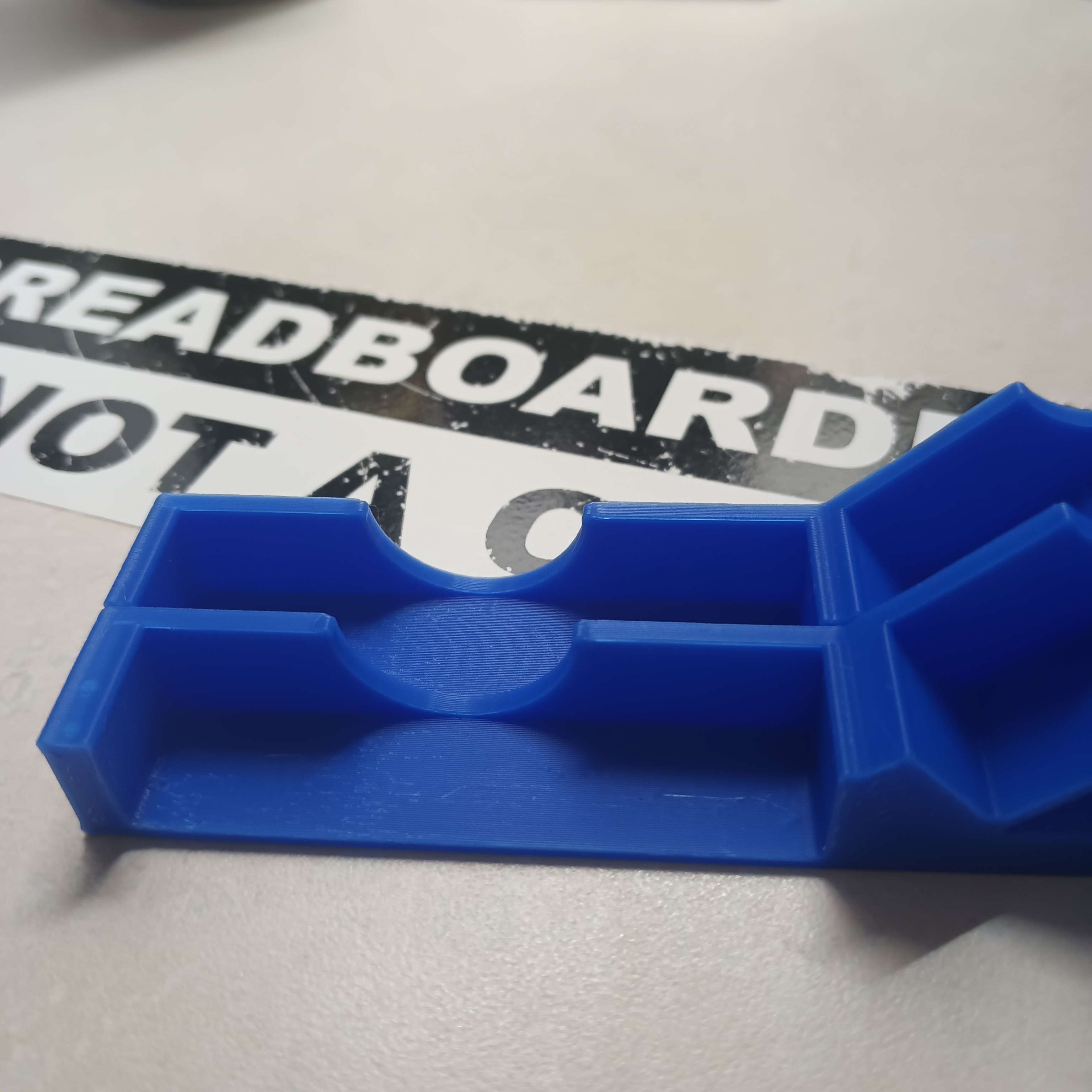
I’ve got proper (I hope) breadboards, and made this V1 rack, which seems to be usable in this state already:
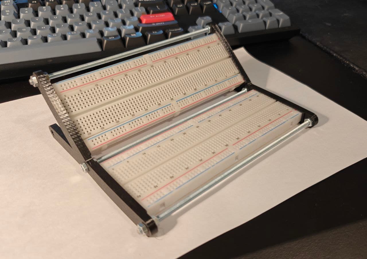
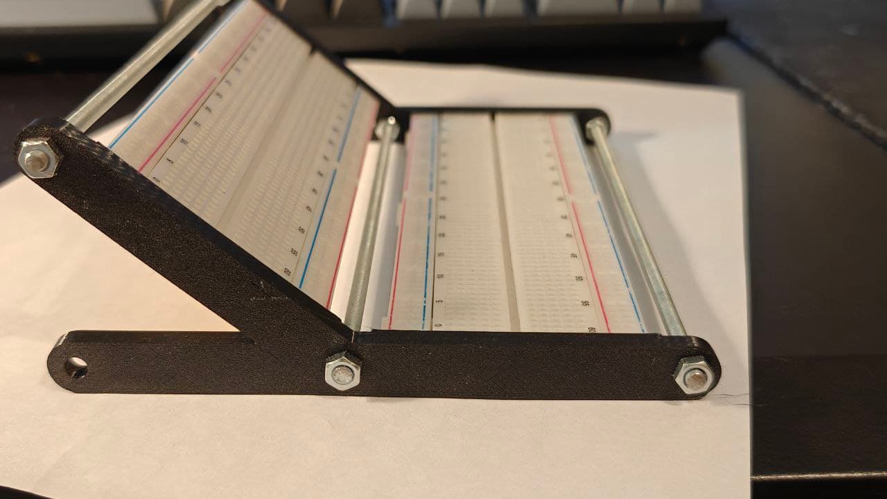
Aside from the need to use metal rods, it’s as minimalistic and filament-efficient as I could make it.
I’ve put the result on thingiverse here: Micro Microrack Rack minimal v1 (breadboard rack) by ignis32 - Thingiverse
3 Likes
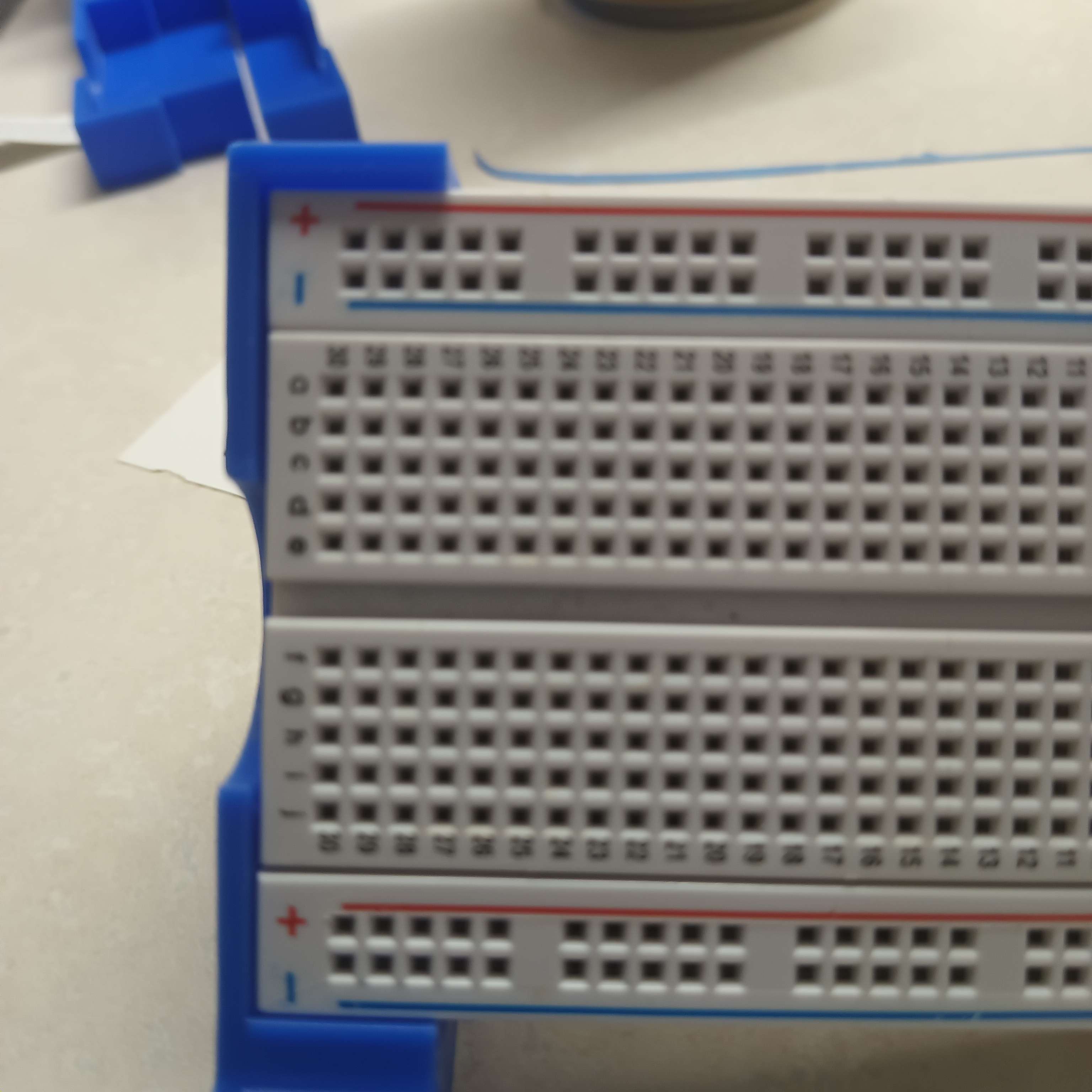
Okay, got mine printed out (without mid-line braces). It works. The middle frame unit is definitely unnecessary, but the initial revision of the minimalist pure 3d printed rack…works.
The middle support is likely unnecessary, but it feels more rigid. There’s a LOT of room in the slots, with the tab clearing completely.
All in all… a solid start. Next revision will feature supports, be slightly narrower (the gap between the wall and the board is about 2.1mm, and have a slot for tabs in the middle section. End sections don’t come in contact with the tabs at all, so it fits fine.
The supports will likely be added to a foot section added to the front and back of the bottom of each section.
1 Like
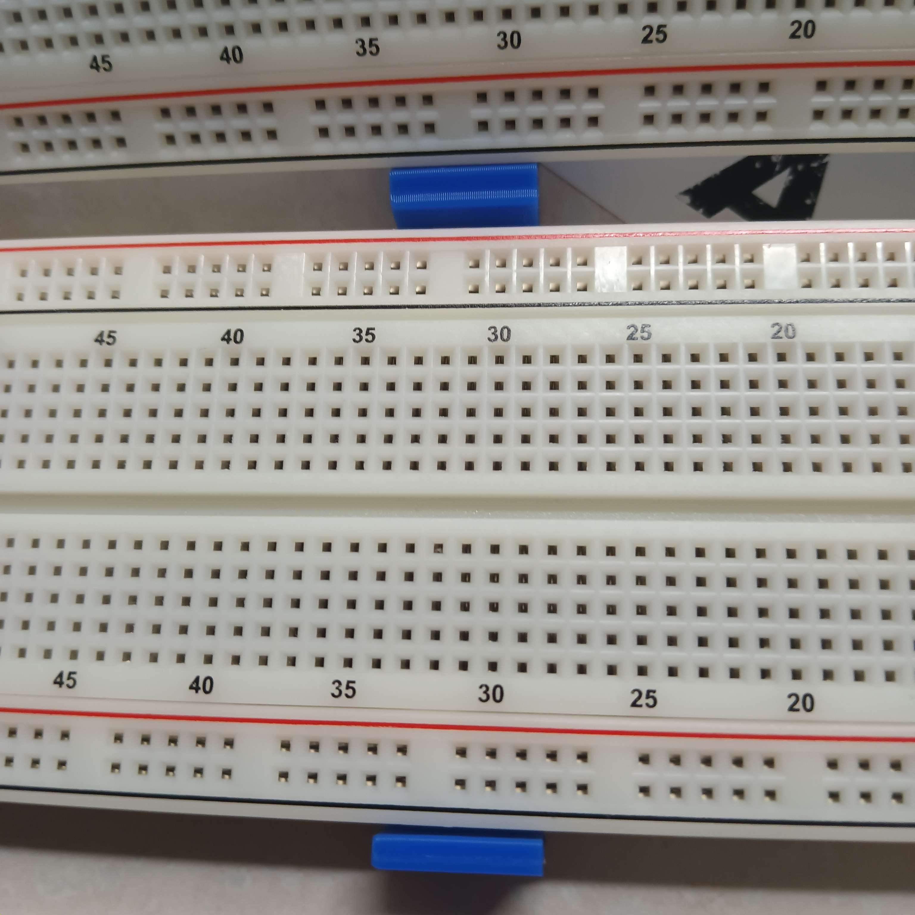
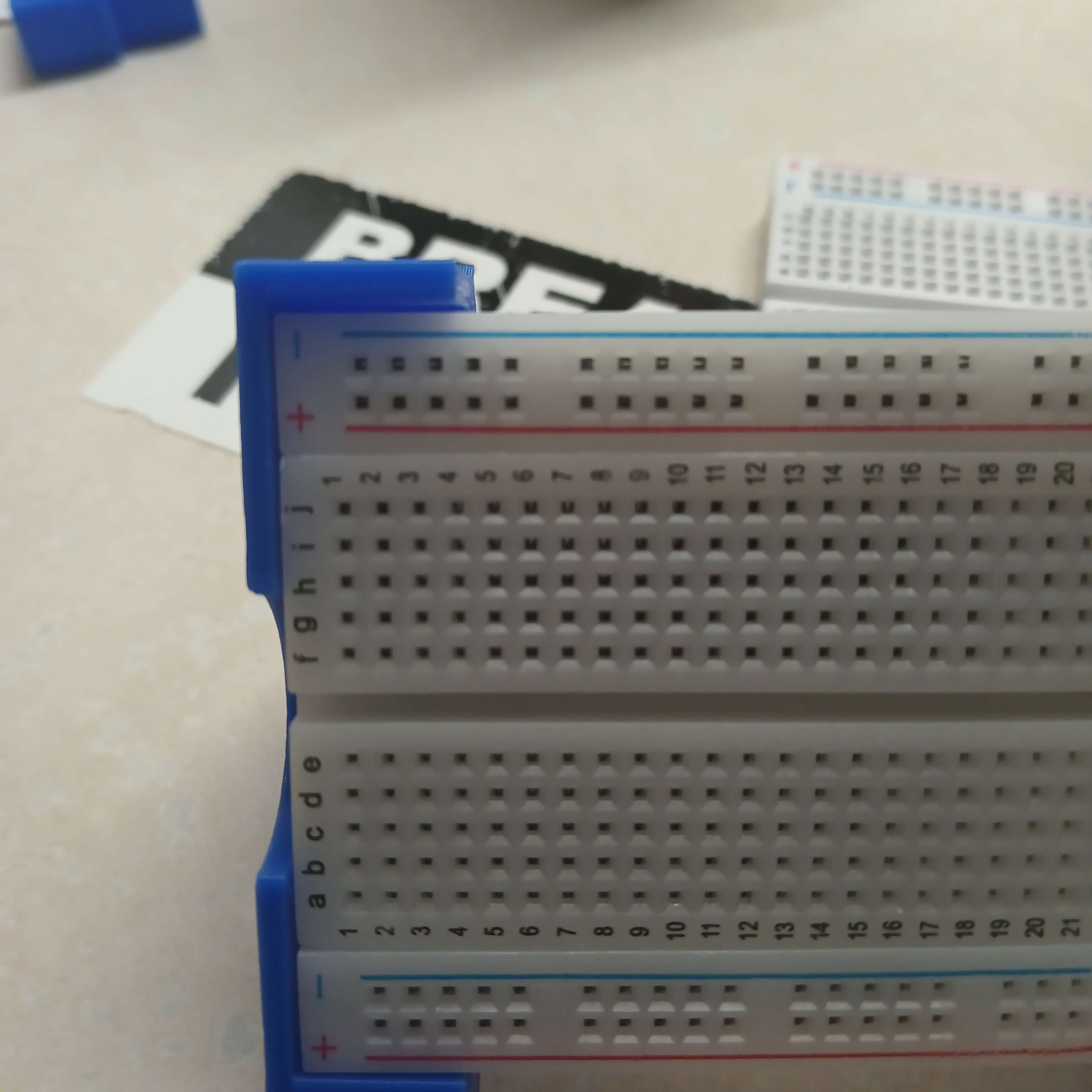
Rev1 has begun. Started with tightening those gaps to hug the board by bringing the bottom module closer to the middle and the top module up a bit.
The board now sits comfortably. I tested all of the breadboards I have on hand and all fit, though one model fits really snugly.
The tight one:
A looser one (Look at the bottom to see some of the angle):
Only the optional middle support needs a cutout because the side pieces are narrow enough. I’ll be designing that and the cross-body supports and grooves for that shortly tonight and tomorrow.
3 Likes
I am not sure about reducing gap between breadboards too much. It is for sure more elegant to have small gap with empty breadboards, but there would be modules with knobs standing out, and wires.
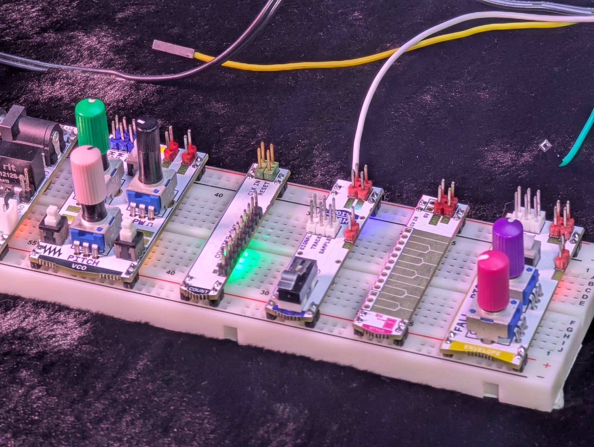
Knobs might be quite high and some of them are on the edge of the modules :
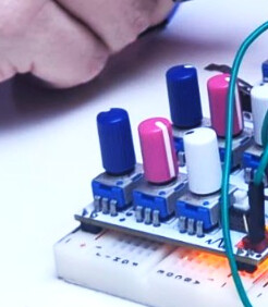
I am concerned that if we would put breadboards too close together while maintaining upper breadboard too vertical - knobs might collide or at least it would be inconvenient to turn, something like this:
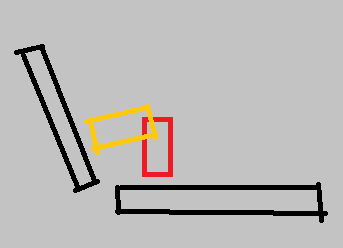
Without actual modules at hand it is hard to determine optimal distance and angle however, so I do not have better recommendation than just paying attention to this potential problem.
Meanwhile I am trying to draw a 3 breadboard variant.
1 Like
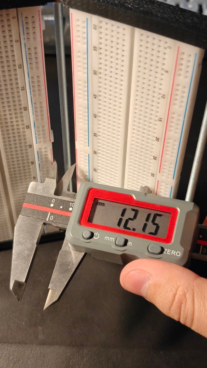
I’ve tried to measure and estimate the knob sizes with this tool: Measure in photo online ‐ eleif.net
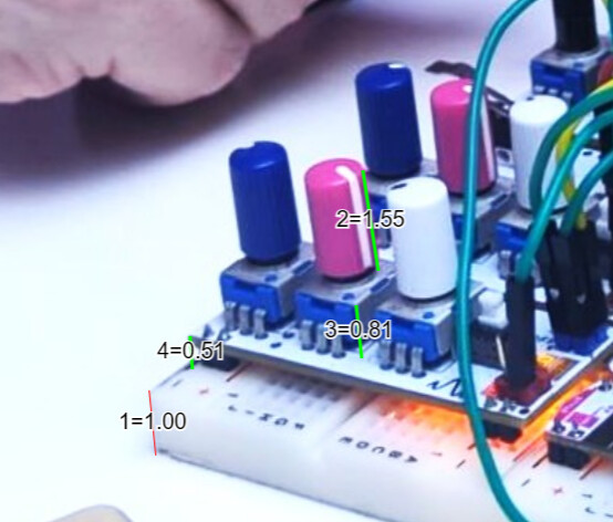
Measurements here are relative to the the first one, so one unit is one breadboard thickness.
Distance from breadboard to the knob top seems to be 2.87 units.
My breadboard thickness is somewhere between 9 and 10 mm (squishy foam on the bottom is just about 1mm thick, so measurement result depends on how much do you press with the calipers)
This gives us from 25.83mm to 28.7 mm height of knob top above the breadboard surface.
Bigger number is most probably correct one - breadboard is not heavy enough to squish the bottom foam on the photo on it’s own.
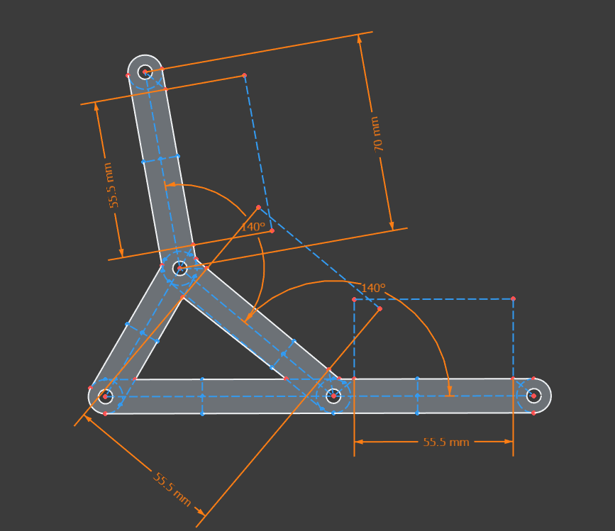
So, rounding up a bit, I would suppose that there should be 3 cm space above each breadboard that should not intersect with other breadboard’s 3 cm space.
And thats least 3cm to avoid collision, without “convenience” reserve.
I would review my blueprints to check if my rack meets that requirement.
3 Likes
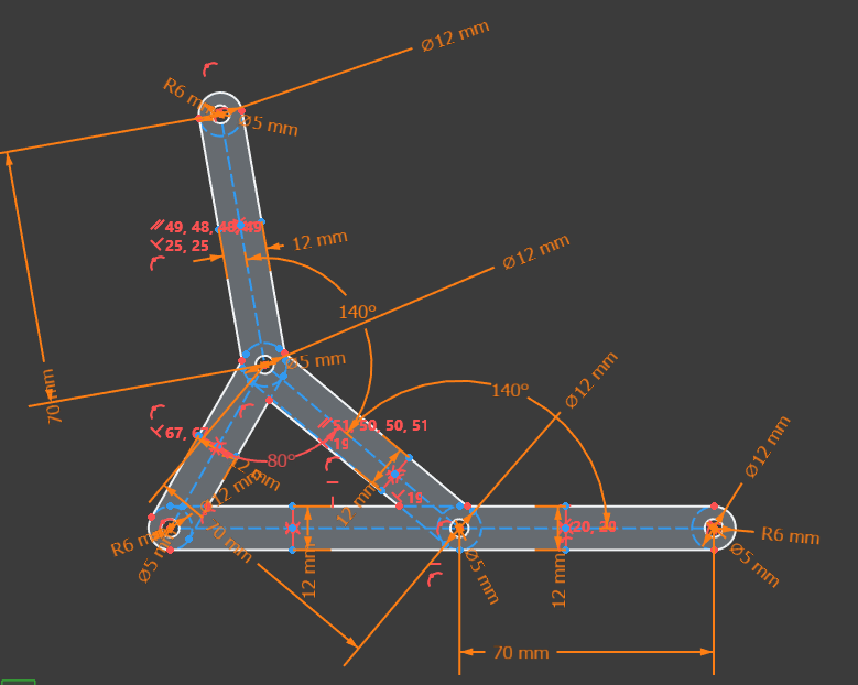
Even with 140 degrees angle and 12mm gap between breadboards (shortest distance) - their 3cm airspace seems to intersect.
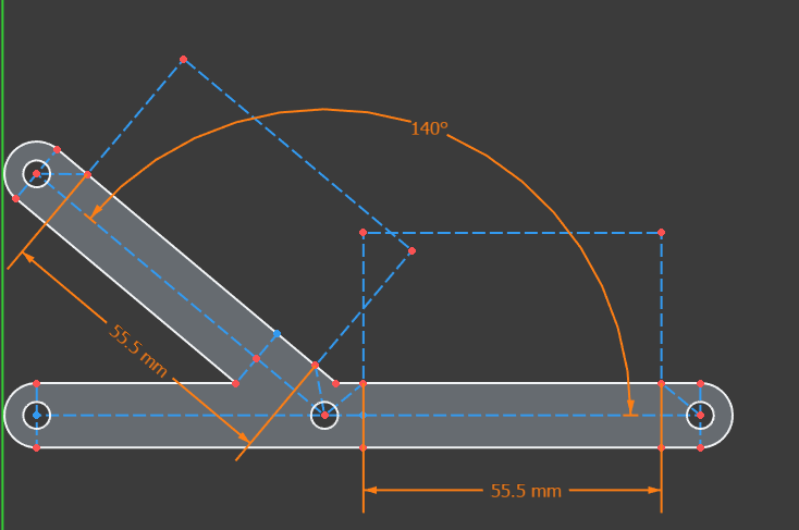
Damn. At first glance - if I did not misssing something, looks like even in my less tight case I would have to increase that gap to be on the safe side.
There is still a chance though - 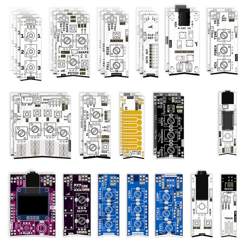
Knobs on the market schematics and demo screenshots tend to be on the bottom of the modules. In other words, they are on the edge, but bottom edge. Top edge is usually dedicated to I/O and CV pins.
WIth that, some airspace intersection might be still not that critical.
1 Like