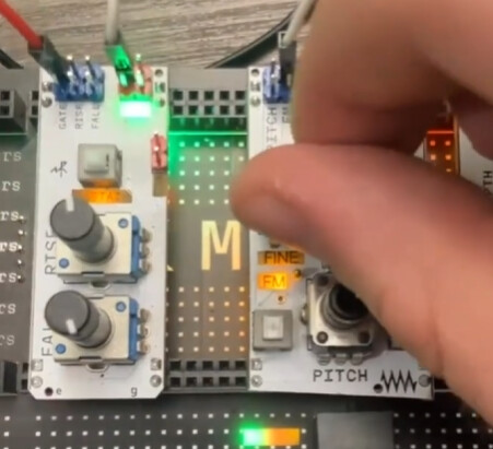
In the end, the gap largely stayed the same and was just adjusted back away from the user. That said, I didn’t realize the knobs were THAT tall (I more based the angle on the Eurorack modules sitting next to me). Not just that, but I didn’t really take the cables into consideration. Easy fixes that’ll go into the next revision. Knowing the gaps has been the biggest issue.
I’ll also be including grooves in the side for 400 boards in case someone wants to not just have 830 boards. It’d be like 3 modules per board max.
Luckily Blender is free and PLA+ is cheap. I can get the general geometry and features and finalize the spacing later.
Edit: yeah, I was thinking that the cables probably don’t require too much height for the rigid sections, but it’s still something I’ll take into consideration.
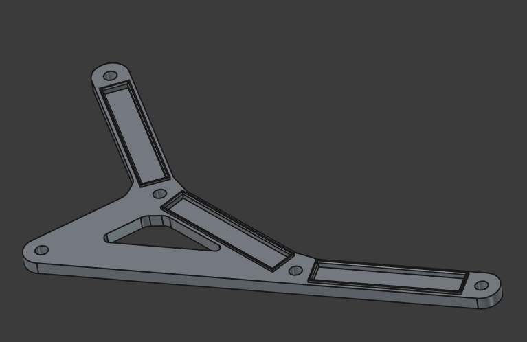
I have a question for the 2 breadboard variant – will it make sense for the support to be a triangle shape as well like the 3 breadboard variant? Idk my brain is thinking about the rigidity of the top breadboard
So, while the rest of the breadboard is unused, I wouldn’t go so far as to say that it’s useless. Think of every row as a passive mult.
Edit: Once the main minimalist rack I’m working on is complete, I’ll make a rails only one just… because I can? I’m also working on the 400 board racks so people can do mini ones.
I am quite happy with rigidity in that direction actually. I’ve printed that to check if it would be enough, because I was not sure - and it seems to be okay. Even with quite low infill.
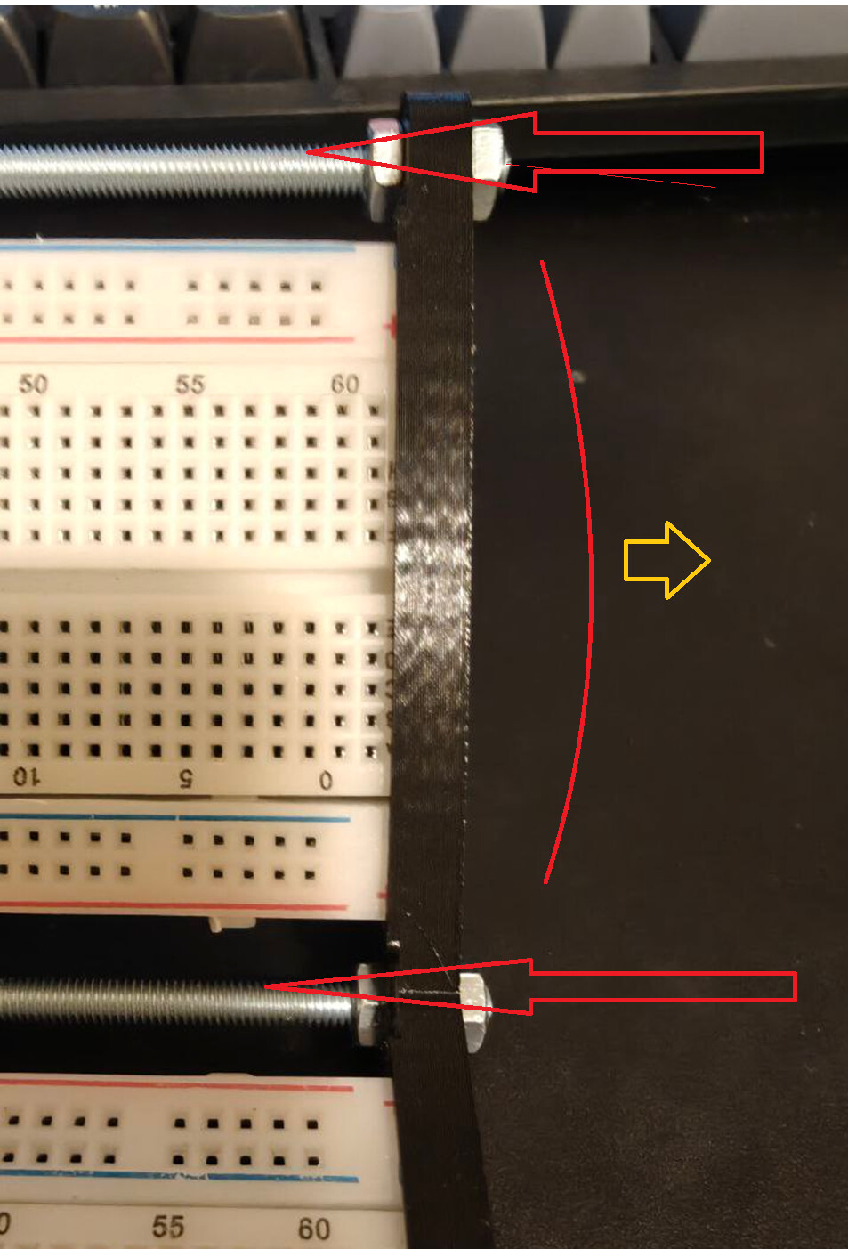
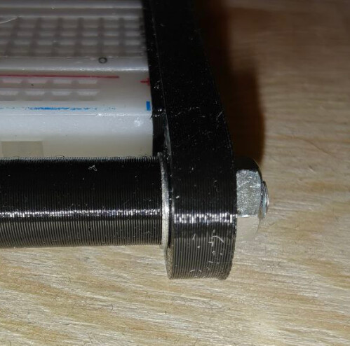
When nuts are too tight. I had to be careful with tightening to evade getting a bow-like shape there. I had to increse walls count and infill to reduce that effect specifically.
I am still not sure actually. And I do not have enough breadboards to scavenge power lines yet. I’ve ordered some, but they would arrive in two weeks, so I have pretty enough time to think. For now I would work on three boards rack I think.
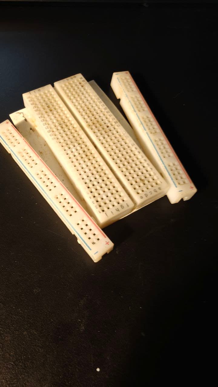
For what it’s worth, all of my power rails are able to be detached and reconnected; it’s the pad/sticky cover that keeps it all firmly connected. Using a utility or hobby knife, you should be able to cut the pad without impacting the ability to reconnect. That said, as we’ve found, your miles may vary.
That’s what I was looking at: two boards held together with tabs making a flat sheet. The reality is that it just needs some wings to fit the width and a way of attaching them. Sure, I could pull off the backing and just stick them to a flat panel, but where’s the fun in that?
I thought about it a bit more critically, and it just occurred to me that the breadboard is technically in the way if we want to hand solder components to both sides of a perfboard (think DIY Eurorack module with more Z height but with fixed X/Y dimensions).
Now the power rails-only rack system seems like a really good idea.
Oh, like if you wanted to make a custom module? I guess, that’s true, but I feel like it goes against the principle of a “breadboard-mounted modular system” which seems like the goal. At that point, you’ll HAVE TO get a custom rack instead of just a standard breadboard.
To that effect… Nothing is stopping Microrack (or yourself actually :D) from selling only breadboard powerlines mounted to a backplate with the correct spacings XD
I’m reaching at this point, but I guess that might not be the goal of Microrack. I backed the project (and will continue to do so) treating it as a miniaturised Eurorack.
I mean, don’t get me wrong. It’s definitely something to consider. I’d almost rather just create risers sets for modules that they can slot into and have the risers slot into the breadboard. This would give height without compromising the standard.
that’s a great idea as well. no doubt we will all be trying different methods to achieve it. We’ll know once fulfillment arrives
I wouldn’t mind trying my method as well with acrylic and the powerlines. It occurred to me as I already have a few ideas in my mind for modules but I have no experience in PCB design so I will have to resort to hand soldering…
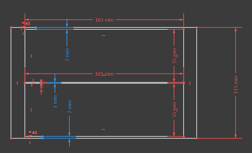
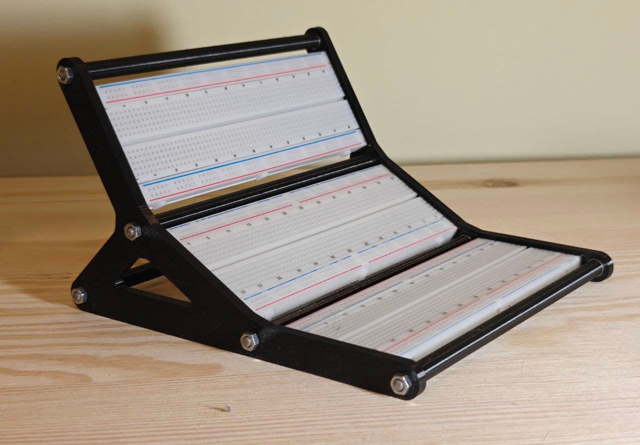
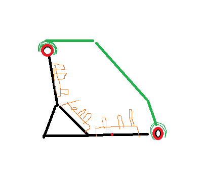
Angle between breadboards is 150 degrees now, to reduce possible intersection between breadboards airspace, and for the top breadboard to be still angled enough.
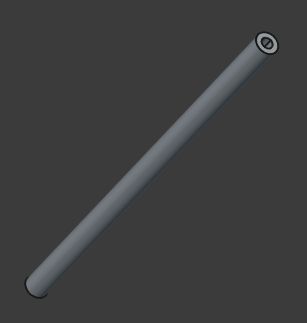
I have added some optional plastic tubes with 4mm inner diameter. Threaded rods are screwed into the tubes with a screw-gun, and sit there tight. They serve several purposes at once:
Hide the metal rods inside for aesthetics and less sharp stuff (threads) to touch.
Reinforce the 4mm rod for more rigidity
Serve as a natural limit when thightening the nuts to evade bending.
(Still needed two washers, one on each side to tune tube’s length a bit)
Once rod is within tube, further assembly seems easier than without a tube.
In the future once i have modules in place, tubes might be a clip-on or hinges location for some kind of a cover-case like that: