Cool! I think we can add serial midi option to the midi configuration screen
2 Likes
Here’s my version if you want to use it as a draft. No switching in the configuration screen though. midi over serial · m-malikov/MOD-ESP32-FW@74953e1 · GitHub
3 Likes
with which program did you document the patch?
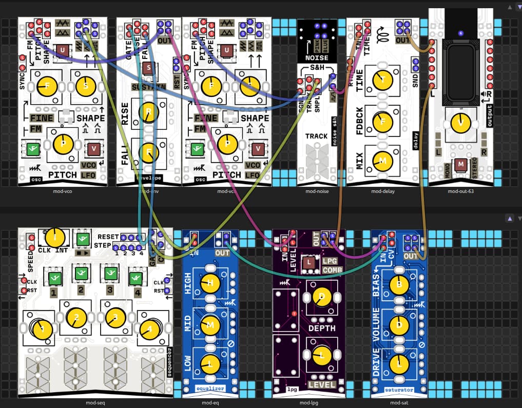
I’m just using diagrams.net for patches you’ve seen at printed cards
And also there is a cool online patcher by @ignis32 : Micropatch
2 Likes
I’m happy to finally get my Microrack! I’m new to modular synthesis, but I got it to make some music on day two.

5 Likes
That’s a ridiculously musical patch. I love it!
1 Like
Here’s a jam of microrack with a few other synths. Myself on microrack and plinky, Jon, Paul, Paul, Dave, Ifeoluwa on synths and Bee on vocals. The seven of us improvised this on our Tuesday night meet up https://drive.google.com/file/d/1ULI-OZfhQyvP8CX9ifFwLXcpjgvJntd0/view?usp=drivesdk
2 Likes

8 Likes
Can you share the patch? It’s absolutely gorgeous.
A short melody-thingy, to sort of prove musical usefulness.
It is really fun, taking signals into my own hands again.
When trying to recreate something specific, it is the same as with any other synth: I get 80% there very quickly, but getting the details right requires endless patience and persistence, which I don’t have.
Another thing I noticed: with Microrack, there is always yet another way to the same goal. Example: replace the sequencer with LFO → clock divider → stylus keyboard. Now you don’t have to tune every single step, because everything is already quantised. Also you can change the gate length (duration) with the “shape” parameter at the oscillator. Here I used the sequencer module, but only for clock and counter, because I absolutely am too lazy to tune things, if avoidable.
Melodically I seem to have had the same idea as @Wes_Virnelson above, but, well, gotta Honour the Ancients first or something. (that bass from "I Feel Love“)

20260308.micropatch.json (8.1 KB)
Edit: the wiring of the actual sequence is not in the JSON-file:
Step 1 → F
Step 2 → nothing (so pitch stays at F)
Step 3 → C
Step 4 → D#
5 Likes
Don’t forget to feed the birds!
3 Likes

2 Likes
Just another short tech demo, demonstrating:
- chaining clock dividers (and a sequencer) for long or complicated sequences
- manual start and automatic stop of a sequence
- badly done drums. Really bad. Pinging a filter is just not enough, it seems.

20260315.micropatch.json (9.8 KB)
Here is the wiring between the counters and the stylus keyboard:
divider 1, step 1 -->|-- c (highest note)
divider 1, step 3 -->|-- c (highest note)
divider 1, step 7 -->|— G#
divider 2, step 1 -->|— G#
divider 2, step 5 -->|— E
divider 2, step 7 -->|— E
divider 3, step 3 -->|-- C (lowest note)
divider 3, step 5 -->|-- C (lowest note)
There are diodes in the wires to compensate for an unexpected interaction between the two modules. The diodes should have low reverse leakage current; any ordinary 1N4148 or similar should do. I used 24V Zener ones (because I could not find my stash of 1N4148s) and it was iffy, took a bit of warm-up to work reliably because Zener diodes are not that great at stopping reverse current (it is, after all, not what they are made for).
I just plugged the diodes straight into the breadboard, using a column as a passive multiple, then a patch wire onto the top wire of the diode, and a black patch wire with the male end to connect the passive mult to the stylus keyboard.
The connection from the stylus pin to RST in of the lower sequencer is not permanent, it is the manual start „button“.
The upper sequencer only serves as a stoppable LFO: when the sequence has reached its end, the last output is connected to the reset input of the upper sequencer, stopping the clock. A reset signal to the last sequencer/counter in the chain clears that “stop” output and starts everything from the beginning again.
4 Likes
Monday evening playing with the lpg and delay.

2 Likes
Using counters to control chord changes and the filter to modulate the sound.

4 Likes

I had an Arduino Nano and a rotary encoder so I wired them up to create a pulse generator with 5 outputs at 1x, 2x, 4x, 8x, and 16x speed. The fast pulses go to the sequencer and slower ones to counters. One of the counters controls the stylo module.
4 Likes
Nice work,
it possible to share our code for pulsegenerator.
1 Like
Here is the pulse generator sketch. I am using an Arduino Nano, but it would work on any Arduino or ESP 32 board with adjustments to pinouts. I hope this helps.
/*
Hardware Connections
  Rotary Encoder:
    CLK to D2
    DT to D3
    SW to D4
    + to 5V
    GND to GND

  Pulse Outputs:
    D5 (1x)
    D6 (2x)
    D7 (4x)
    D8 (8x)
    D9 (16x)

  Onboard LED:
    D13 (mirrors 4x pulse on D7)

Rotate the rotary encoder to increment the number
of milliseconds to wait between pulses.

Click the rotary encoder to increment by 10 ms

Long click the rotary encoder to decrement by 10 ms
*/

//install the Encoder library by Paul Stoffregen
#include <Encoder.h>

// Pin Definitions
const int pulsePins[] = {5, 6, 7, 8, 9};
const int multipliers[] = {1, 2, 4, 8, 16};
const int swPin = 4;
const int ledPin = 13; // Onboard LED

// Timing Constants
const unsigned long pulseWidth = 15;
const int nMin = 20;
const int nMax = 2000;
const unsigned long longPressThreshold = 500;

// State Variables
int n = 125;
unsigned long masterStartTime;
unsigned long swDownTime = 0;
bool swWasPressed = false;
bool longPressExecuted = false;

Encoder myEnc(2, 3);
long oldPosition = -999;

void setup() {
  for (int i = 0; i < 5; i++) pinMode(pulsePins[i], OUTPUT);
  pinMode(ledPin, OUTPUT);
  pinMode(swPin, INPUT_PULLUP);

  Serial.begin(9600);
  resetSync();
}

void loop() {
  handleEncoder();
  handleSwitch();
  handlePulses();
}

void resetSync() {
  masterStartTime = millis();
  for (int i = 0; i < 5; i++) digitalWrite(pulsePins[i], LOW);
  digitalWrite(ledPin, LOW);
  Serial.print("Sync Reset. n = ");
  Serial.println(n);
}

void handleEncoder() {
  long newPosition = myEnc.read() / 4;
  if (newPosition != oldPosition) {
    // Keep 1ms fine-tuning on the rotation
    n += (newPosition > oldPosition) ? 1 : -1;
    n = constrain(n, nMin, nMax);
    oldPosition = newPosition;
    Serial.print("n = ");
    Serial.println(n);
  }
}

void handleSwitch() {
  bool swIsPressed = (digitalRead(swPin) == LOW);

  if (swIsPressed && !swWasPressed) {
    swDownTime = millis();
    longPressExecuted = false;
  }

  // Long Press: Decrement n by 10
  if (swIsPressed && !longPressExecuted) {
    if (millis() - swDownTime >= longPressThreshold) {
      n = constrain(n - 10, nMin, nMax);
      Serial.print("Long Press (-10ms): ");
      resetSync();
      longPressExecuted = true;
    }
  }

  // Short Press: Increment n by 10
  if (!swIsPressed && swWasPressed) {
    if (!longPressExecuted) {
      n = constrain(n + 10, nMin, nMax);
      Serial.print("Short Press (+10ms): ");
      resetSync();
    }
  }
  swWasPressed = swIsPressed;
}

void handlePulses() {
  unsigned long currentMillis = millis();
  unsigned long elapsed = currentMillis - masterStartTime;

  for (int i = 0; i < 5; i++) {
    unsigned long interval = (unsigned long)n * multipliers[i];
    unsigned long timeInCycle = elapsed % interval;
    bool isHot = (timeInCycle < pulseWidth);

    digitalWrite(pulsePins[i], isHot ? HIGH : LOW);

    // D7 is index 2 (1x=D5, 2x=D6, 4x=D7)
    if (i == 2) {
      digitalWrite(ledPin, isHot ? HIGH : LOW);
    }
  }
}
3 Likes

3 Likes